Design conditions
Power conditions
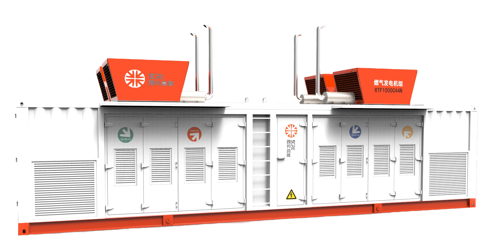
According to the electrical load of the project, our company proposes to equip 18 MW gas generator sets+6 sets of booster and transformer skid (containerized tpye,to boost to 10 kV)+1 set of 10 kV sub-section post+1 set of step-down transformer skid. By feeding 18 set of 1MWgas generator set to 6 box type transformer skids respectively, the 400 V voltage is boosted to 10 kV and then converged to 10 kV sub-section post, and the sub-section post supplies power to the refrigeration compressor. At the same time, part of the electrical energy is output to the step-down transformer skid, 400V electric energy is distributed by step-down transformer skid.
According to the actual power load of the project, 1~2 set of 1MW gas generator sets (also know as 1000kw gas genset) can be shut down, which can be switched for use in subsequent generator maintenance. A set of remote station control system is recommended for the project, which can observe the specific operation of the generator set in the central control room. The flue gas of gas generator set is used for waste heat utilization, and the 1MW unit is equipped with DN300 flue gas header and flange.
One high-voltage power supply provided by the user is 10KV±5% 50HZ±0.5HZ, three-phase three-wire system, and the neutral point is not grounded. The direct burial of armored high-voltage cables is introduced.
Design scope
Party B is responsible for the design of the 10KV/0.4KV substation and the power supply and distribution system of the liquefaction plant (with the power receiving pile head of the 10KV incoming cabinet as the boundary), responsible for the design of the high and low voltage electrical system diagrams, electrical control schematic diagrams, and Terminal diagram, reference layout diagram of high and low voltage electrical equipment, and local operation box (column) design. Power distribution of Utility of the whole plant, power supply of the main electric pump of the fire protection system, public lighting of the whole plant, building lighting system, emergency power supply of diesel generators, and maintenance distribution boxes (cabinets) are not within the scope of this design.
Design and selection principles
(1) The electronic control equipment of this liquefaction plant shall strive to be reliable, safe, advanced and easy to operate on the premise of meeting the design conditions and process requirements.
(2) The control, measurement, protection and signal of all motors and electrical equipment shall be set in accordance with the relevant national regulations.
(3) The 0.4KV system in the factory is designed as a double circuit.
(4) All process electrical equipment is equipped with local operation control boxes (cabinets). The explosion-proof grade of local electric control equipment in explosion-proof areas is designed according to DⅡBT4, and its protection grade is IP65; the outdoor protection grade of electric control equipment in non-explosion-proof areas is IP54 Design, the protection level of indoor electronic control equipment is designed according to IP30.
(5) When the high and low motors are started, the bus voltage should meet no less than 85% of the rated voltage. For this reason, low-voltage motors with a rated power of 75KW and above are required to start with a soft starter; the main motor of the refrigerant compressor adopts a high-voltage solid state Soft start device.
(6) The high-voltage system adopts a microcomputer integrated protection device to realize functions such as relay protection and metering.
(7) The operation, protection and signal power of the high-voltage switchgear adopts a DC power supply of DC220V, which comes from a maintenance-free lead-acid battery DC screen, and the DC power supply is shared with the 10KV system.
( 8) The operating status of the electrical equipment of the entire liquefaction equipment and the current signal of the motor of 30KW and above enter the DCS system for display, and all electrical equipment of the process equipment can be started and stopped on the DCS in the central control room, and can also be started and stopped locally. Emergency stop buttons for refrigerant compressors, feed gas compressors, circulating water pumps, etc. Are set in the central control room.
(9) The microcomputer comprehensive protection device of the medium voltage system is distributed and installed on each switch cabinet, and a microcomputer background monitoring system is set up. The 10KV system background monitoring system is shared with the 35KV background monitoring system, and no separate setup is required. Realize the monitoring of power consumption parameters of the liquefaction plant, the quality monitoring of the grid power supply, remote control of equipment, measurement and alarm functions, report management, trend analysis, statistics, and recording of all electrical parameters of the liquefaction plant.
(10) The 10KV high-voltage system is equipped with a dynamic reactive power centralized compensation device to perform reactive power compensation for high-voltage equipment. After compensation, the bus power factor is greater than 0.95. The low-voltage system is equipped with a non-contact switching reactive power compensation device to perform reactive power compensation on the 380V bus. After compensation, the power factor of the bus is greater than 0.95.
Post time: Jan-09-2023


