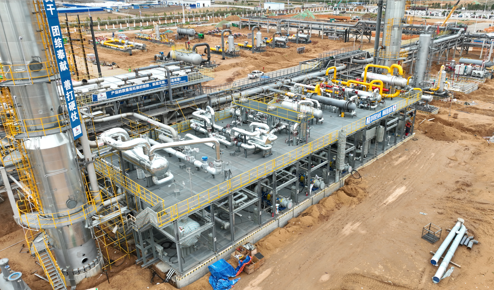
 the main units introduction:
1 .1 Wellhead gas throttling, pressure reduction, cooling and three-phase separation system
1) Process flow description
The natural gas from the gas well is throttled and depressurized, and cooled by the feed gas cooler before entering the three-phase separator. Under the action of gravity, due to the difference in density between oil and water, the free water sinks to the bottom of the container, and the oil floats to the top and climbs over the oil-water barrier. The plate enters the oil chamber, and the float-type liquid level regulator controls the crude oil discharge by operating the oil drain valve to maintain the stability of the oil level. The separated free water is discharged through the drain valve controlled by the oil-water interface regulator to maintain the stability of the oil-water interface. The separated oil enters the stabilizer to further separate the water, and then enters the oil storage tank, where it accumulates to a certain amount and is sold to oil sellers. The separated moisture enters the sewage treatment system through the closed discharge system and is discharged after passing the treatment. The separated natural gas is divided into 6 trains after pressure stabilization, filtering and metering, and the natural gas with a flow rate of 5 MMSCMD is sent to 6 trains of natural gas desulfurization devices respectively . The main process equipment of each unit is 6 three-phase separators, 6 natural gas coolers, flow meters (purchased by the owner) .
2) Design parameters
Flow rate of Feed gas into the device: 28.3 MMSCMD
Inlet pressure: 7400 psig
Outlet pressure: 1218 psig
3) Adaptation range
The load adjustment range is 50%~100 % .
1.2Ⅰ~ Ⅵ series natural gas desulfurization devices
1) Process flow description
The Feed gases enter the I~ VI series natural gas desulfurization units respectively. This unit uses the MDEA solution to remove acidic gases such as CO2 and H2S in the feed gas.
Natural gas enters from the lower part of the absorption tower and passes through the absorption tower from bottom to top; the fully regenerated MDEA solution (lean liquid) enters from the upper part of the absorption tower and passes through the absorption tower from top to bottom. The MDEA solution and natural gas flowing in the opposite direction are in the absorption tower. After full contact, the CO2 and H2S in the gas are absorbed and enter the liquid phase. The unabsorbed components are led out from the top of the absorption tower and enter the desulfurization gas cooler and separator. The gas leaving the desulfurization gas separator enters the I~ VI series molecular sieve dehydration device, and the condensate goes to the flash tank.
H2S content in the processed natural material is less than 5 mg/Sm3.
MDEA that has absorbed H2S is called rich liquid and is sent to the flash evaporation tower. The natural gas flashed out by decompression is sent to the fuel system. After the flashed rich liquid exchanges heat with the solution (lean liquid) flowing out from the bottom of the regeneration tower, the temperature is raised to ~98°C to the upper part of the regeneration tower, where stripping and regeneration is performed in the regeneration tower until the lean liquid degree of the lean liquid reaches the target.
The lean liquid coming out of the regeneration tower passes through the rich-poor liquid heat exchanger and the lean liquid cooler. The lean liquid is cooled to ~ 104°F . After being pressurized by the lean liquid pump, it enters from the upper part of the absorption tower.
The gas at the top outlet of the regeneration tower passes through the carbon dioxide cooler and enters the carbon dioxide separator. The gas exiting the carbon dioxide separator is sent to the carbon dioxide emission system. The condensate is pressurized by the reflux pump and sent to the regeneration tower .
The heat source of the reboiler of the regeneration tower is provided by the medium temperature heat transfer oil from the heat transfer oil system .
The acid gas removed by the desulfurization system is directly discharged into the atmosphere. Basically no wastewater is discharged, and the water taken away by acid gas is discharged through the supplementary desalted water balance system; the water removed by the dehydration system enters the sewage treatment system through the closed discharge system and is discharged after passing the treatment.
2) Design parameters
The flow rate of Feed gas into the absorption tower is 5 MMSCMD for each train
Absorption tower operating pressure: 1218 psig
Absorption tower operating temperature: 104°F ~ 140°F
Regeneration tower operating pressure: 7.25 psig
Regeneration tower operating temperature: 203°F ~ 239°F
The heat source for the reboiler of the regeneration tower is medium temperature thermal oil ( 320°F ).
H2 S gas in the desulfurization gas is 5 mg/Sm3
3) Adaptation range
The load adjustment range is 50%~100 %.
1.3Ⅰ~ Ⅵ series natural gas dehydration devices
1) Process description
This device uses temperature swing adsorption technology for gas separation and purification. Temperature swing adsorption technology is based on the physical adsorption of gas molecules on the internal surface of the adsorbent (porous solid material). The adsorption capacity of the adsorbent for gas changes with the adsorption temperature and pressure. Under the condition that the adsorbent selectively adsorbs different gas components, it adsorbs certain components in the mixed gas at low temperature and high pressure, and the un-adsorbed components flow out through the adsorber layer, and desorbs these adsorbed components at high temperature and low pressure. For the next low-temperature and high-pressure adsorption, multiple adsorption towers can be used to achieve the purpose of continuous gas separation.
The feed gas drying unit is equipped with three adsorbers for switching operation, including one for adsorption, one for cold blowing, and one for heating and regeneration.
The feed gas drying unit uses a small amount of Feed gas as a cold blowing and regeneration medium. After the regenerated gas leaves the adsorption tower, it is cooled and separated and then compressed by a booster and sent to the adsorption tower for adsorption.
The regeneration gas first passes through the cooled adsorber from top to bottom. Then the regeneration gas is heated to the regeneration temperature of 392~428 ° F by the regeneration heater, and then enters from the bottom of the adsorber to desorb the water adsorbed by the adsorbent. The regeneration gas comes out from the top of the dryer, is cooled by the regeneration cooler, and then enters the regeneration gas separator. After the liquid is separated, it enters the supercharger and is compressed and sent to the adsorption tower for adsorption.
After passing through this unit, the water in the dry natural gas is ≤ 15 ppm.
2) Design parameters
Feed gas processing capacity: 5MMSCMD
Operating pressure: 1210 psig
Adsorption temperature: 104 °F
Regeneration method: isobaric regeneration
Regeneration temperature: 392~428 ° F
Regenerative heat source: thermal oil
2 O in the purified gas ≤ -20 ℃
3) Adaptation range
The load adjustment range is 50%~100 % .
Contact us:
Sichuan Rongteng Automation Equipment Co., Ltd.
www. rtgastreat.com
E-mail: sales01@rtgastreat.com
Phone/whatsapp: +86 138 8076 0589
Address: No. 8, Section 2 of Tengfei Road, Shigao Subdistrict,Tianfu New Area, Meishan city, Sichuan China 620564
Post time: Sep-28-2023


