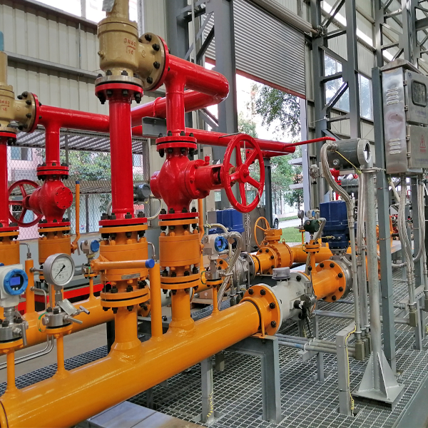
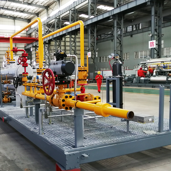
Key point of RMS design includes the following items:
- Pipe Line sizing calculation and design
- Knock-out Drum / Filter Separator / Liquid Separator sizing calculation and design
- Dry Gas Filter sizing calculation and design
- WBH sizing calculation
- Regulator, Relief Valves and SSV sizing calculation
Basic terms
Before discussing design of RMS, we need to discuss the following terms:
- Gauge Pressure and Absolute Pressure
- Standard Volume and Actual Volume
The absolute pressure is measured relative to the absolute zero. All calculation involving the gas laws requires pressure (and temperature) to be in absolute units.
Atmospheric pressure is pressure in the surrounding air at – or “close” to – the surface of the earth. The atmospheric pressure depends on the temperature and altitude above sea level. The Standard Atmospheric Pressure is 14.696 Psi (1.01325 bar).
A gauge is often used to measure the pressure difference between a system and the surrounding atmosphere. This pressure is often called the gauge pressure and can be expressed as:
Pg = Pa – Po
Where:
Pg = Gauge Pressure Pa = Absolute Pressure
Po = Atmospheric Pressure
Standard Volume indicates a gas volume in a Standard Condition (standard temperature and temperature condition), while the Actual Volume indicates a volume in an Operation Condition.
In industry and commerce, standard conditions for temperature and pressure are often necessary to define the standard reference conditions to express the volumes of gases and liquids and related quantities such as the rate of volumetric flow. In the last five to six decades, professionals and scientists using the metric system of units defined the standard reference conditions of temperature and pressure for expressing gas volumes as being 0 °C (273.15 K;32.00 °F) and 101.325 kPa (1 atm). During those same years, the most commonly used standard reference conditions for people using the imperial or U.S. customary systems was 60 °F (15.56 °C; 288.71 K) and 14.696 psi (1 atm). This definition of Standard Condition was almost universally used by the oil and gas industries worldwide. However many technical publications just simply state “standard conditions” without specifying them, often leading to confusion and errors.
The following formula (F-2) shows the relationship between Standard Volume and Actual Volume:
(F – 2)
Where:
Vb = Volume at standard condition, or Standard Volume Vm = Volume at operation condition, or Actual Volume Pb = Absolute pressure at standard condition
P = Absolute pressure at flow condition
Tb = Absolute temperature at standard condition, K T = Absolute temperature at flow condition, K
Zb = Compressibility factor at Standard condition Z = Compressibility factor at flow condition
In RMS design, usually we use flow rate instead of volume. In that case, volume Vm and Vb can be replaced by flow rate Qm and Qb.
Where:
Qm = Actual Flow Rate. Qb = Stand Flow Rate.
For pipe size estimation, Z and Zb can be considered as 1.0.
Post time: Oct-22-2021


